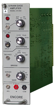
MODEL 610 STRAIN GAGE AMPLIFIER ASSEMBLY
Description
The Model 610 strain gage amplifier provides the performance characteristics and control for the most demanding applications. Featuring low output noise, user selectable gain and frequency response and a host of other conveniences, the Model 610 offers maximum performance at a moderate price.
Specifications
| Bridge configuration: | Quarter dynamic and full bridges are switch selectable on the front panel. Static and half bridges are selectable by changing the internal completion header. This unit also can be used as a general purpose differential amplifier |
| Bridge completion: | Internal header mounts customer-specified precision completion resistors |
| Bridge excitation: | Front panel adjustable 1.25VDC to 15.0VDC constant voltage excitation or fixed 15mA or 30mA constant current excitation; front panel on/off switch |
| Bridge balance: | Front panel trimpot allows bridge to be manually balanced |
| Operating modes: | Switch selects Zero, AC coupled, External cal signal, DC coupled, or DC cal |
| Gain: | Front panel switch selectable gains of 1, 2, 5,10, 20, 50, 100, 200, 500, 1000, 2000, 5000 with gain vernier |
| Frequency response: | DC to 50kHz, with board-mounted dip switch selectable two-pole active filter at 10Hz, 500Hz, 1kHz, 5kHz, 16kHz, and 32kHz -3dB frequencies |
| AC coupled response: | Board-mounted toggle switch selects 10Hz highpass or 0.4Hz highpass filter |
| CC limit: | Front panel LED lights if bridge wiring resistance exceeds constant current excitation capabilities |
| Output noise: | 5 microvolts RMS RTI max, DC to 32kHz at G=1000 |
| Power: | Model 819-003 power supply module provides unregulated ±24V to all 610 modules in enclosure |
| Mechanical: | 19″W x 5.25″H x 14″D, seven-module rack adapter, Model 4007-145 |
| Carrying case: | One- and two-module desktop cases, Model 4009-104 and Model 4010-106 |
| Calibration: |
Activated by front panel Mode switch or remote command; places internal calibration resistors across bridge
|
|
|
Activated by front panel Mode switch or remote command; signal applied to rear panel BNC is connected to amplifier input
|
||
|
Signal outputs:
|
Main
|
±10V max., 100mA peak load |
|
Tape
|
±10V max., 5mA peak load |

